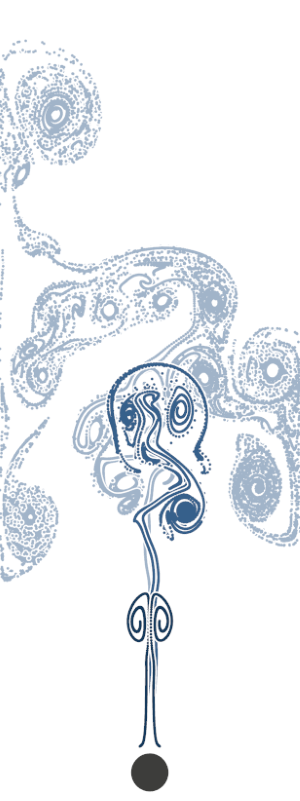
Flow around a cylinder
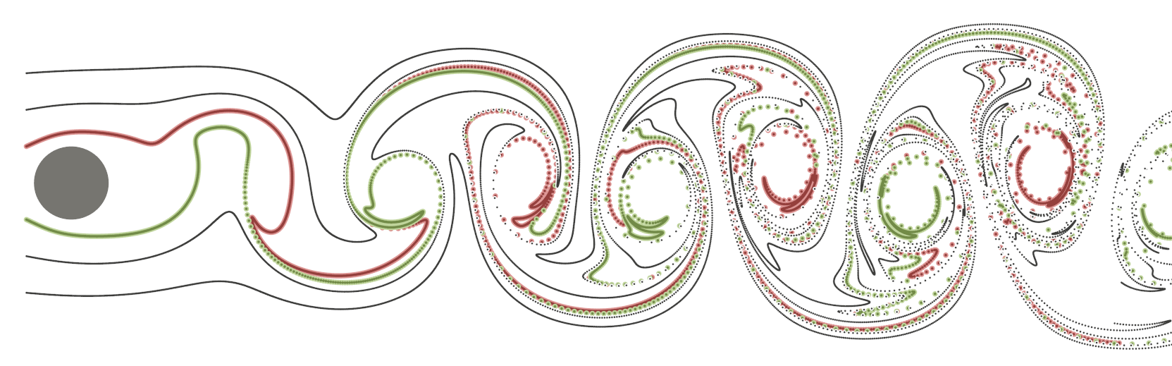
- Streak particles illustrating the flow around a cylinder. The two innermost particle streaks are coloured red and green, in order to highlight the two most turbulet streaks in this illustration.
The video below shows two particle streaks injected into a flow around a cylinder. The particles are coloured for better differentiation of the two streaks, when tey start intermixing due to turbulence.
Flow around a rectangle
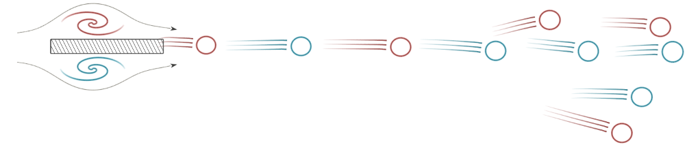
- Illustration of vortex motion. Two path lines indicate the general direction of flow around the rectangular obstacle. Vortices spawned by the obstacle are coloured red and cyan, to indicate a clockwise and counter clockwise rotation direction respectively. By illustrating vortices, their trajectories and path lines, this image successfully illustrates the past (speed lines), present (vortices) and future (path lines) of this flow field.
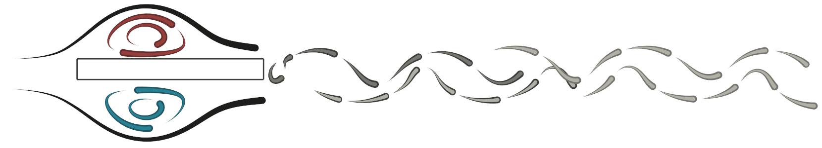
- Pathlets are used to illustrate vortices and dynamic behaviour. Pathlines below and on top of the obstacle are coloured red and cyan in order to underline vortical behaiour.
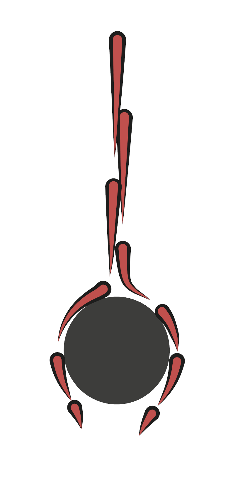
Flow around a triangle
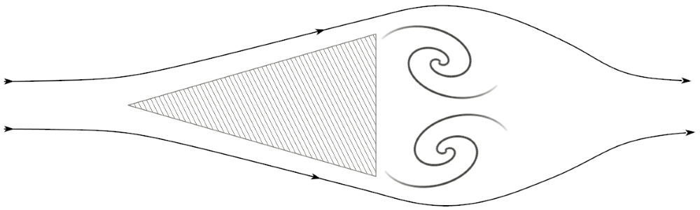
- Two stream lines and two vortex templates illustrate the stationary flow field after 110 time steps. The stream lines are displayed with three additional arrow glyphs each, to encode the direction of flow. The vortx templaes on the other hand are displayed without additional arrow glyps. This can be done, because their respective direction of rotation can be intuitively understood by their appearance and the general direction of flow.
Flow around three triangles
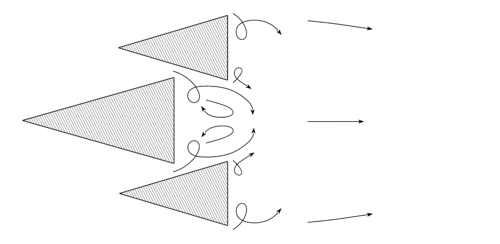
- Pathlines starting near the corners of the three triangular obstacles illustrate particle trajectories, starting at the first time step. Arrow glyphs ath the end of each path line encode the direction of flow. The path lines reveal strong turbulence directly behind the three obstacles.
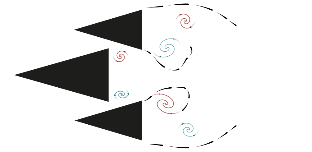
- Streamlets and vortex templates illustrate the stationary flow field after 50 time stps. The vortex colour underlines the rotation direction of the vortices, using red for clockwise and cyan for counter clockwise rotation direction, respectively.
Flow around three rectangles
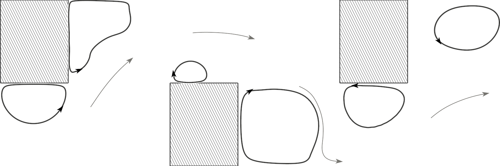
- Technical illustration of the flow around three rectangular obstacles. Four grey stream lines illustrate the general direction of flow. The black stream lines near the obstacles illustrate closed stream lines.
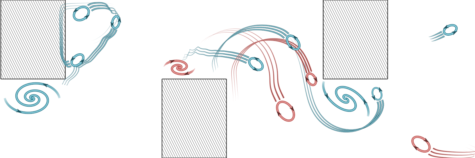
- Illustration of vortex motion over 75 time steps. Vortices that exhibit a strong motion are depicted ellipses in order to put more emphasis on the aspect of their motion. Stationary vortices or vortices that exhibit little motion are depicted as spirals, to underline their swirling behaviour.
This video shows four tracked vortices. Two with clockwise and counter-clockwise rotation direction, each. Additionally, for each vortex, its trajectory over the past 100 time steps is illustrated, using three speed lines. The vortices are merely depicted as ellipses, in order to put more emphasis int the aspect of their motion, than their swriling behaviour.
Boussinesq flow
|
|